READ THESE INSTRUCTIONS COMPLETELY BEFORE
BEGINNING!
If you are in doubt about any of the procedures, have a qualified automotive electrician install the system for you!
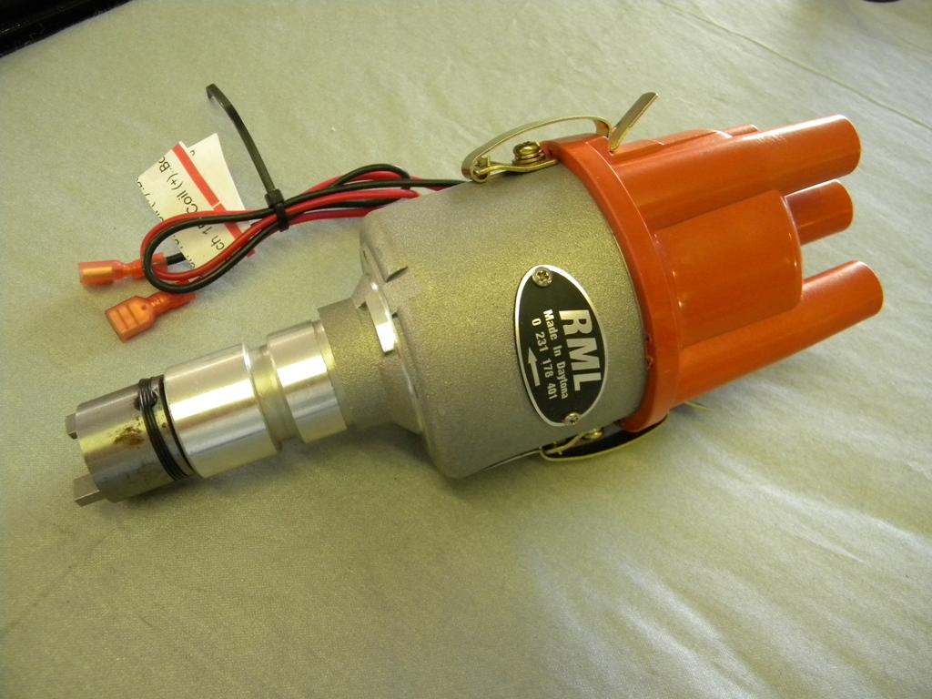
- This is an electronic ignition distributor containing an electronic module, which is to be used only in 4-cylinder applications and 12-volt negative ground systems.
- Use this distributor with the Bosch Blue 12-volt coil provided.
- Coil resistance must be 3-4 ohms across the primary .
- We recommend the BOSCH BLUE COIL
Use of any other coil will cause damage to the module and void any warranty.!!!
START HERE:
WARNING…WARNING…WARNING
PUT TRANSMISSION IN NEUTRAL OR PARK,
SET THE EMERGENCY BREAK AND BLOCK WHEELS.!!
MAKE SURE THE IGNITION SWITCH IS OFF!
The wire from the ignition switch to the ignition coil primary terminal is NOT used in many applications. If this wire is allowed to touch vehicle or engine ground, with the ignition switch on, it can cause a direct short on the battery, possibly causing permanent damage to the vehicle wiring and a fire.
RML Automotive Inc, assumes no liability for damage caused from this occurrence or due to any faults in the existing vehicle wiring.
DISTRIBUTOR INSTALLATION
Bring engine to TDC, #1 Cylinder firing (both valves closed and distributor rotor pointing to #1 cylinder of distributor cap). In this condition the “P” mark should be aligned with the pointer on th crankshaft.
IMPORTANT!!
DO NOT ROTATE THE ENGINE AFTER YOU REMOVE THE
DISTRIBUTOR!
Remove distributor, o-ring and clamp. Inspect o-ring and replace if necessary. Install clamp and o-ring on the new 401 distributor. Install distributor in engine, making certain the offset drive fully engages the oil pump driveshaft.
Helpful Hint!
(I recommend installing the distributor without the o-ring so you can get a clear idea of where the rotor wants to fall when the drive gear engages the oil pump. When you are sure of how it wants to engage, remove the distributor and then install the o-ring. Now you know exactly where the rotor wants to point when the off-set drive engages.)
Rotate the distributor body until the rotor once again points to #1 cylinder on the distributor cap. Lightly tighten the clamp to distributor. Final timing must be done with a timing light at the completion Performance Ignition installation.
NOTE!
’82-’89 MOTRONIC SPIDERS
The distributor clamp on these cars is fitted with a tamper-proof bolt that must be ground or cut off, so that the clamp can be reused. A new 6x1x40mm bolt and nut is supplied in parts bag.
COIL MOUNTING + WIRING
The Bosch Blue Coil –.PART* 9.220.081.083 — is a direct replacement for the original coil, so it will fit where your old coil fits.
- The red wire must be connected to the positive (+) or (15) side of the coil.
- The black wire must be connected to the negative (-) or (1) side of the coil.
- Electronic tach signal can be taken from coil negative or (1)
SETTING THE IGNITION TIMING
We have found that the 401 Series Distributor set between 5° and 10° BTDC at 750 to 900 RPM gives the most power throughout the RPM range. It is difficult to be specific about the ideal ignition timing for YOUR car’s engine; experimentation will yield the best results. The aim is to achieve maximum performance and throttle response without pre-ignition (pinging).
If you any questions beyond the scope of these instructions feel free to call RML Automotive Inc. at 386-258-0243.


1 Responses to 4101E Instructions